
Your partner for LPG solutions
Your partner for LPG solutions
STATIC LPG STORAGE TANKS FOR BURIED INSTALLATION
PED 2014/68/EU
CAPACITY: 15 – 20 – 25 – 30 – 35 – 50 MC
TECHNICAL DETAILS
Construction Code:EN 13445-3
Approval: PED 2014/68/EU
Certification:CЄin accordance with EN 17065
Category: IV
Shell and Head Materials:P355NH – UNI EN 10028-3
Material Certificates:EN 10204 – 3.1
Operating Pressure:17,65 bar – (20,00 bar) (if requested)
Design Temperature:-20 °C +50 °C
Hydrostatic Test Pressure:25,24 bar – (30,00 bar) (upon request)
Contained fluid:LPG
Welding coefficient:1 – (0,85) (upon request)
Safety coefficient: 2,4 – (2,7) – (3,0) (upon request)
INSPECTIONS, TESTS AND ACCEPTANCE
Compliant with PED, EN 12542 and EN 13445
NDT: UT, VT, PT, (RT) (upon request)
FINISHING
External protection of the tank through a surface finishing that ensures corrosion protection:
Sandblasting grade SA 2,5
Two-component epoxy paint. Thickness: 500 microns
Alternative solutions can be provided to cater to specific consumer requirements.
DATA SHEET
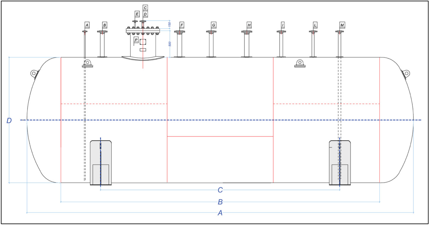
| PRODUCT CODE | C.ty[mc] | A [mm] | B [mm] | C [mm] | D [mm] |
| NCVIN_DEP_15MC_1700-OR | 15 | 6.940 | 6.000 | 4.500 | 1.700 |
| NCVIN_DEP_20_2370MC-OR | 20 | 5.300 | 4.000 | 2.500 | 2.370 |
| NCVIN_DEP_25_2370MC-OR | 25 | 6.300 | 5.000 | 3.700 | 2.370 |
| NCVIN_DEP_30_2370MC-OR | 30 | 7.300 | 6.000 | 4.500 | 2.370 |
| NCVIN_DEP_35_2370MC-OR | 35 | 8.300 | 7.000 | 5.700 | 2.370 |
| NCVIN_DEP_50_2370MC-OR | 50 | 12.300 | 11.000 | 4.750 (x2) | 2.370 |
STANDARD CONNECTIONS

| ID | Nominal Flange Diameter | Function |
| A | DN 15 | Draining |
| B | DN 65 | Max level alarm |
| C | DN 25 | Thermometer (without pocket) |
| D | DN 25 | Level Rod |
| E | DN 15 | Pressure gauge |
| F | DN 80 | Safety valves manifold |
| G | DN 65 | Level gauge |
| H | DN 80 | Free connection |
| I | DN 50 | Filling |
| L | DN 40 | Gas phase withdrawl |
| M | DN 40 | Liquid phase withdrawl |
| P | DN 450 | Manhole |
EQUIPMENT ON REQUEST
On request, buried LPG static storage tanks are supplied with service and safety equipment according to D.M 13/10/1994 and D.P.R n. 151 of 01/08/2011.
Equipment list:
a. Safety valves;
b. Safety valves manifold, suitable to cut-off one valve at a time for maintenance;
c. Safety valves steel vent pipe;
d. Liquid level gauge;
e. Max liquid level alarm;
f. Pressure gauge with electric contacts for max pressure alarm;
g. Liquid phase thermometer;
h. Extractable level rod;
i. Liquid phase withdrawl with wafer ball valve and excess flow valve;
j. Gas phase withdrawl with wafer ball valve and excess flow valve;
k. Filling valve with Check valve;
l. Command board;
m. Inspection manhole DN450;
n. Cathodic protection:
n. 4 anodes of 8,5 kg with 10 mt cable + 1 electrode 150×300 (tanks of capacity up to 30 mc) n. 6 anodes of 8,5 kg + 1 electrode 150×300 (tanks of capacity between 30 and 50 mc)
n. 1 steel plate with a 15 mt cable to be fixed to the tank
n. 25 mt cable for a ring connection
Please note that the installation of a cathodic protection system is strongly recommended, and shall be verified by the designer in function of installation place.